


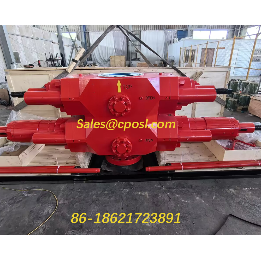
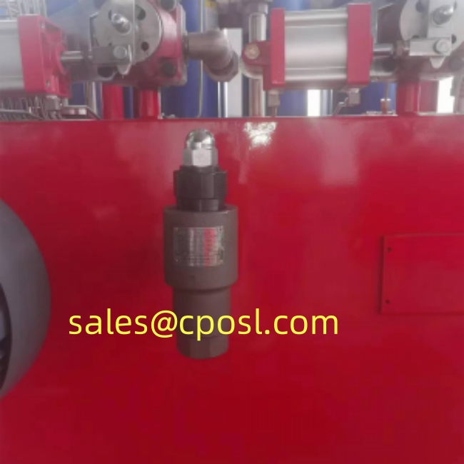
ASME-certified bladder accumulators for BOP control systems. Energy storage, hydraulic shock absorption, and pump pulsation dampening. Compatible with low-lubricity fluids. Fast response time.
ASME Standard Bladder Accumulator | High Pressure BOP Hydraulic Accumulator
Description
I. Functions
Accumulator functions as following in a hydraulic system: Storing of energy, stabilizing of pressure, reduction of power, compensation of leakage, absorbing of fluctuation of pressure and buffering of impact.
II. Specification
1. Structure: Bottom repair structure, top repair structure.
2. Fastening Method: Dead ring or bearing.
3. Installation: Vertical.
4. Medium: Hydraulic oil, emulsion
5. Gas filled in the bladder: Nitrogen
III. Installation
1. Accumulator shall be installed vertically with the gas valve upright. Inspection space shall be retained near gas valve.
2. Accumulator shall be fixed tightly on the supporter or wall.
3. When used for buffering and absorbing the fluctuation, accumulator shall be placed near the fluctuation source.
4. Check valve shall be placed between accumulator and hydraulic pump to prevent return flow of oil for the accumulator when the electric machine of pump stops working.
5. Stop valve shall be placed between accumulator and pipe system to be used in gas charging, draining speed adjusting or long term stopping.
6. Welding shall not be applied in fixing the accumulator.

Reviews
There are no reviews yet.