
API 6A / API 7K Drilling Fluid (Mud) Manifold — central high-pressure distribution hub connecting triplex mud pumps to the standpipe. 2″-5″ bore, 5,000-10,000 psi WP, PSL 1-3, Material Class AA-EE, NACE MR0175. Double-loop hammer-union or flanged configuration.
CAMTOP Drilling Fluid Manifold | API 6A Mud Manifold 2-5″ 5K-10K psi
£0.00
Description
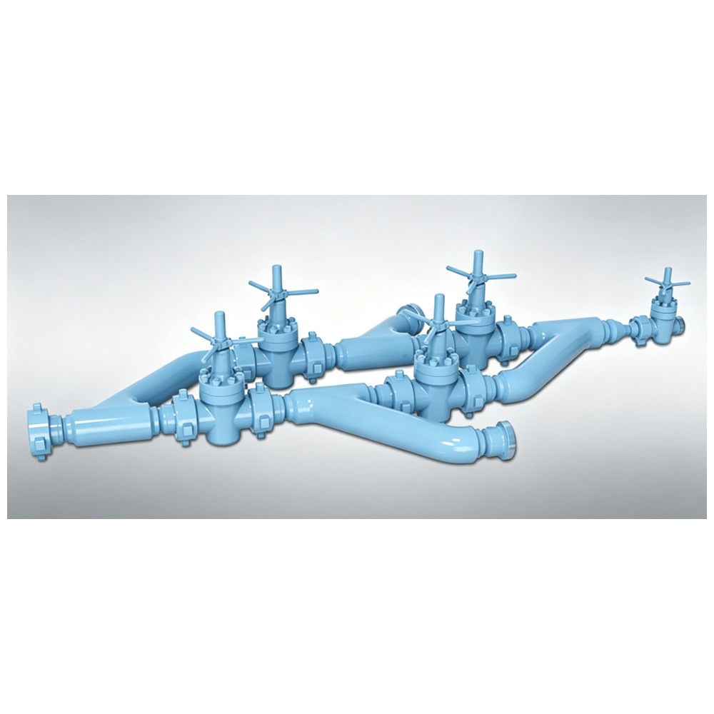
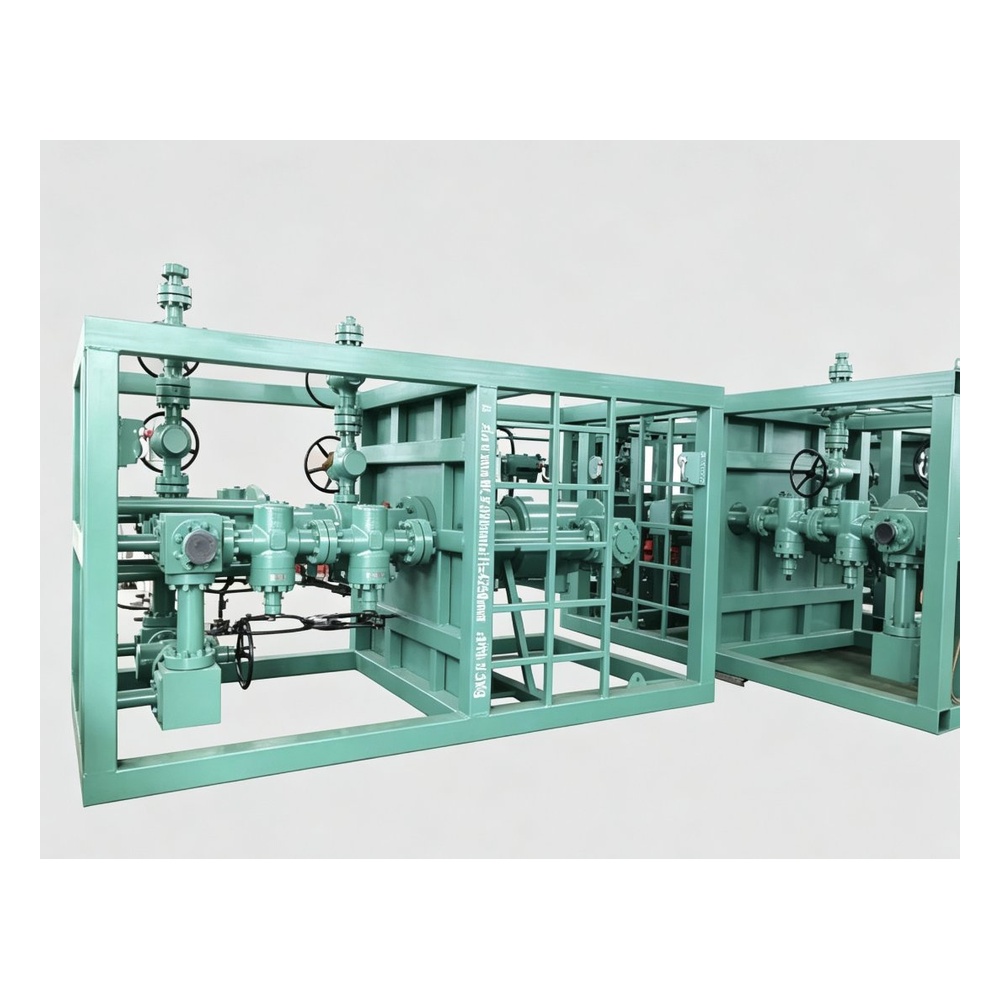
The CAMTOP Drilling Fluid Manifold (also known as Mud Manifold) is the central high-pressure distribution hub connecting your triplex mud pump to the wellbore. Designed and manufactured to API 6A / API 7K, this skid-mounted manifold assembly integrates multiple API 6A mud gate valves, hammer-union or flanged line pipe, fittings and instrumentation into a compact, surface-tested circulating system. CAMTOP delivers 2″, 3″, 4″ and 5″ bore variants from 5,000 to 10,000 psi working pressure with PSL-1 to PSL-3 and NACE MR0175 sour-service compliance.
The manifold functions as the master distribution point between the mud tank / mud pit and the standpipe / rotary hose, allowing drilling crews to route drilling fluids to multiple destinations, isolate individual circuits, switch between pumps, bleed off pressure, and respond to well-control events without interrupting drilling. Every CAMTOP Drilling Fluid Manifold is hydrostatically tested to 1.5× working pressure, debris-tested with drift gauges, and shipped with full MTC 3.1 / API Q1 documentation.
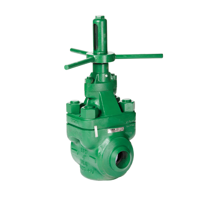
Product Image
Key Features
- API 6A / API 7K Design Standard — full monogram compliance (latest edition applicable), plus NACE MR0175 sour-service materials throughout all pressure-containing parts.
- Quad Bore Coverage: 2″ / 3″ / 4″ / 5″ — four nominal line sizes to match every flow-rate requirement from slim-hole to deep-well drilling.
- Three Pressure Ratings: 5,000 / 7,500 / 10,000 psi — full API 6A pressure-tier coverage with PR-1 (Standard) and PR-2 (Cold Working) options available.
- Full PSL Coverage: PSL-1 / PSL-2 / PSL-3 — performance levels certified for standard, severe-service and offshore applications.
- Five Material Classes: AA / BB / CC / DD / EE — carbon steel, low-temperature carbon, stainless-clad, full 316SS and high-alloy (Inconel 625 overlay) trim options.
- Full Temperature Range: K to U (-60°C to +121°C) — arctic through HPHT service without derating.
- API 6A Mud Gate Valves (Manual, Hydraulic, Pneumatic or Electric) — full-bore, hard-faced seats with renewable trim, replaceable gland packing and grease-injection fittings.
- Hammer Union or API 6A Studded/Flanged Connections — selectable on every line termination; Fig 1502 hammer unions or 6B / 6BX flanges supplied to client specification.
- Double-Loop (Parallel) Header Design — primary and bypass loops with crossover valves allow uninterrupted circulation during maintenance.
- Pressure Relief & Bleed-Off Valves — manual or spring-loaded relief mounted on every discharge branch for safe depressurization.
- Pressure Gauges, Sample Ports & Drain Valves — instrumentation tees at every critical point for real-time monitoring of pump discharge and standpipe pressure.
- Skid-Mounted Structural Frame — welded carbon-steel skid with lifting lugs, fork-lift pockets and pre-painted (offshore / onshore) finish, fully transport-ready.
- Sour-Service Trim (NACE MR0175) — SS316 / Inconel 625 internals, Viton / HNBR / AFLAS elastomers and controlled-hardness bolting.
- Hydrostatic Test Certificate — every manifold shell tested to 1.5× WP, seat test at 1.1× WP, drift test, PMI and dye-pen penetrant before shipment.
Technical Specifications
| Parameter | Specification |
|---|---|
| Product Type | Drilling Fluid (Mud) Manifold — suction / discharge assembly |
| Design Standard | API Spec 6A (latest ed.), API Spec 7K, ASME B31.3 |
| Nominal Bore Sizes | 2″ / 3″ / 4″ / 5″ (DN50 / DN80 / DN100 / DN125) |
| Working Pressure Ratings | 5,000 psi (5K) / 7,500 psi (7.5K) / 10,000 psi (10K) |
| Pressure Class | PR-1 (Standard) / PR-2 (Cold Working) |
| Product Specification Level (PSL) | PSL-1 / PSL-2 / PSL-3 |
| Material Class | AA / BB / CC / DD / EE |
| Temperature Rating | Class K (-60°C) to Class U (+121°C) |
| Body Material | ASTM A216 WCB / A352 LCC / A351 CF8M (316SS) |
| Trim (Valve Seats & Gates) | 17-4PH H1150 / SS316 with Stellite 6 overlay / Inconel 625 (NACE) |
| Seal / Elastomer | NBR / Viton / HNBR / AFLAS (per fluid & temp) |
| Bolting | ASTM A193 B7 / B7M / B16 / B16M + A194 2H / 2HM / 7 / 7M / 8 |
| Connection Types | Hammer Union (Fig 1502) / API 6A Studded / Flanged (6B / 6BX) |
| Valve Quantity (Standard Layout) | 4 – 8 mud gate valves (per client P&ID) |
| Configuration | Single-loop, Double-loop (parallel), or Multi-branch (per spec) |
| Actuation | Manual handwheel / Gear operator / Hydraulic / Pneumatic / Electric |
| Pressure Relief | Spring-loaded R3 or R5 relief valves (per ASME Section VIII) |
| Instrumentation | Pressure gauges (0 – 1.5× WP), sample ports, drain valves, bleeders |
| Skid Frame | Welded carbon-steel frame, primer + epoxy finish, lift lugs, fork pockets |
| Corrosion Protection | Offshore-grade coating system per ISO 12944 C5-M (optional) |
| Service | Standard / Sour Service (NACE MR0175) / Low-Temp / HPHT |
| Testing & Certification | Hydrostatic 1.5× WP / Drift / PMI / Dye-Pen / Magnetic Particle / MTC 3.1 |
| Standards Compliance | API 6A Monogram, API 7K, NACE MR0175, ISO 9001, API Q1 |
Available Size & Pressure Configurations
| Model | Bore | Working Pressure | Test Pressure | Standard Connections |
|---|---|---|---|---|
| CAMTOP-DFM-2-5K | 2″ (DN50) | 5,000 psi | 7,500 psi | Fig 1502 Hammer Union |
| CAMTOP-DFM-2-7.5K | 2″ (DN50) | 7,500 psi | 11,250 psi | Fig 1502 Hammer Union |
| CAMTOP-DFM-3-5K | 3″ (DN80) | 5,000 psi | 7,500 psi | Fig 1502 Hammer Union / API 6A Studded |
| CAMTOP-DFM-3-7.5K | 3″ (DN80) | 7,500 psi | 11,250 psi | Fig 1502 Hammer Union / API 6A Studded |
| CAMTOP-DFM-3-10K | 3″ (DN80) | 10,000 psi | 15,000 psi | API 6A Studded / Flanged 6BX |
| CAMTOP-DFM-4-5K | 4″ (DN100) | 5,000 psi | 7,500 psi | Fig 1502 / API 6A Studded |
| CAMTOP-DFM-4-7.5K | 4″ (DN100) | 7,500 psi | 11,250 psi | API 6A Studded / Flanged 6B |
| CAMTOP-DFM-4-10K | 4″ (DN100) | 10,000 psi | 15,000 psi | API 6A Flanged 6BX |
| CAMTOP-DFM-5-5K | 5″ (DN125) | 5,000 psi | 7,500 psi | API 6A Flanged 6B |
| CAMTOP-DFM-5-7.5K | 5″ (DN125) | 7,500 psi | 11,250 psi | API 6A Flanged 6B |
| CAMTOP-DFM-5-10K | 5″ (DN125) | 10,000 psi | 15,000 psi | API 6A Flanged 6BX |
How the Drilling Fluid Manifold Works
Drilling fluid is drawn from the mud tank / mud pit by the suction side of the triplex mud pump (e.g. F-500 / F-800 / F-1300 / F-1600 / BOMCO 1600). The pressurized fluid enters the manifold through the suction header, passes through isolating and throttling mud gate valves, and exits through the discharge header to the standpipe, rotary hose, and finally the top-drive or kelly. CAMTOP typically designs the manifold with a primary loop and a bypass (secondary) loop:
- Primary Loop — standard flow path for routine drilling; carries 100% of circulating volume.
- Bypass Loop — allows isolation of the primary line during valve maintenance without interrupting circulation.
- Crossover Valves — connect the two loops so flow can be re-routed within seconds.
- Pressure Gauges — installed at pump discharge, manifold outlet and standpipe for real-time ECD monitoring.
- Relief Valves — protect against thermal-pressure buildup and pump over-pressure.
- Sample / Drain Ports — for drilling-fluid sampling and full-bore blow-down.
The double-loop architecture means that operators can isolate a leaking valve, depressurize the affected section, and re-route mud through the bypass loop — all without shutting down the rig. This is the principle difference between a CAMTOP mud manifold and a single-line piping arrangement.
Drilling Fluid Manifold vs Choke Manifold vs Kill Manifold
| Function | Drilling Fluid Manifold | Choke Manifold | Kill Manifold |
|---|---|---|---|
| Primary Purpose | Distribute drilling mud from pump to standpipe | Control formation pressure & flow rate from well | Pump kill-weight fluid into well for well control |
| Location | At the rig floor / mud pump area | Between BOP & mud-gas separator | On the rig floor near BOP |
| Standard | API 6A / API 7K | API 16C | API 16C |
| Direction of Flow | Pump → Standpipe | Well → Separator | Pump → Wellbore |
| Key Component | API 6A Mud Gate Valves | Adjustable Choke Valves | FLS Gate Valves |
Application Scenarios
- Onshore Drilling Rigs — land-based conventional and pad drilling rigs requiring mud circulation distribution.
- Offshore Drilling Platforms — jack-up, semi-submersible, and drillships (C5-M coating available).
- Slim-Hole / Slim-Bore Drilling — 2″ / 3″ variants for reduced-diameter circulation loops.
- Deep Well / HPHT Drilling — 10,000 psi and higher with Inconel 625 trim and Class U temperature rating.
- HPHT Service — sour wells (H₂S / CO₂), high-temperature wells, Class CC material and above.
- Workover Rigs — same manifold used for fluid transfer during workover, drillstem test (DST), and completion operations.
- Coiled Tubing Units (CTU) — fluid-feed to CT reel and CT injector.
- Snubbing / Hydraulic Workover Units (HWO) — pulling tubular under pressure requires reliable manifold distribution.
Quality Assurance & Testing
Every CAMTOP Drilling Fluid Manifold is manufactured, inspected, and tested under a documented quality program:
- Material Test Certificates (MTC 3.1) — full traceability per EN 10204.
- Hydrostatic Shell Test at 1.5× rated WP (every line and valve body).
- Hydrostatic Seat Test at 1.1× rated WP (every gate valve).
- Drift Test with gauge to verify unobstructed bore after fabrication.
- Positive Material Identification (PMI) on all alloy components.
- Magnetic Particle / Dye Penetrant Examination on all pressure-bearing welds.
- Functional Valve Test — every mud gate valve opened/closed under rated pressure 5× before sign-off.
- NACE MR0175 Sour-Service Compliance — verified by hardness survey.
- API 6A Monogram — products can be supplied with the official API mark (license # on request).
Why Choose CAMTOP
- 10+ Years’ API 6A Expertise — every manifold designed by engineers who build them every day.
- 4 Bore Sizes × 3 Pressure Ratings = 11 Standard Models — every configuration in stock or short-cycle production.
- Hammer-Union or API Flanged — we’ll match your existing rig terminations.
- Full NACE MR0175 Sour-Service — built-in option for H₂S / CO₂ environments.
- Fast Lead Time — 4–8 weeks for standard configurations, 8–12 weeks for custom designs.
- One-Stop Skid Solution — manifold, mud valves, fittings, instrumentation and skid shipped as a single pre-tested package.
Ordering Information
When ordering your Drilling Fluid Manifold, please provide the following information for the most accurate quote:
- Bore Size — 2″ / 3″ / 4″ / 5″ (DN50 / DN80 / DN100 / DN125).
- Working Pressure — 5,000 / 7,500 / 10,000 psi.
- PSL & Material Class — PSL-1 / 2 / 3, AA / BB / CC / DD / EE.
- Connection Type — Hammer Union (Fig 1502) / API 6A Studded / Flanged 6B / Flanged 6BX.
- Quantity & Type of Mud Gate Valves — 4 / 6 / 8 valves; manual / hydraulic / pneumatic / electric.
- Service — Standard / Sour (NACE) / Low-Temp (-60°C) / HPHT.
- Layout — Single-loop / Double-loop / Multi-branch P&ID.
- Instrumentation — Pressure gauges, sample ports, relief valves (specify quantity).
- Project Documentation — MTC 3.1 / PMI / NDT / Third-Party Witness required?
Contact CAMTOP for Orders & Technical Support
Email: sales@cposl.com
Phone: +86-18621723891
Address: Shanghai, China
Reviews
There are no reviews yet.