
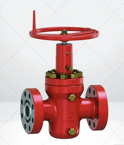
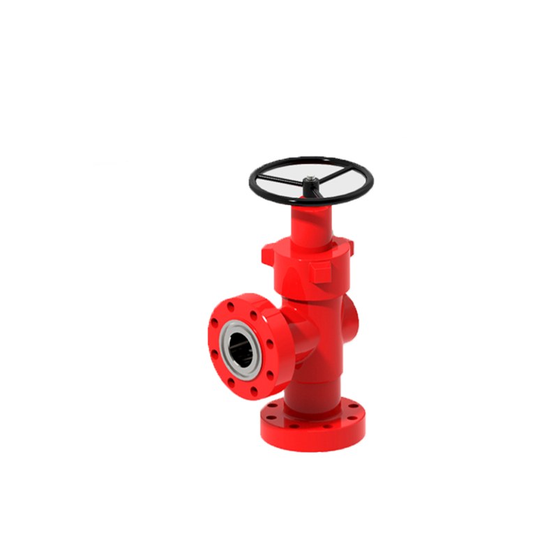
The CAMTOP Model M Threaded End Gate Valve is a premium oilfield wellhead isolation valve available in 2000, 3000, and 5000 PSI working pressure ratings. Features precision threaded ends, ergonomic handwheel operation, full-bore design. Sizes 2-1/16″ to 4-1/16″. Manufactured per API 6A standards with forged alloy steel construction. Request your quote today!
CAMTOP Model M Threaded End Gate Valve | 2000/3000/5000 PSI Wellhead Gate Valve
Description
CAMTOP Model M Threaded End Gate Valve
High-performance wellhead gate valve designed for reliable flow control in oil and gas drilling operations. Available in 2,000 / 3,000 / 5,000 PSI working pressure ratings with precision-threaded end connections.
2000/3000/5000 PSI
Threaded End
API 6A Compliant
Oilfield Equipment
Threaded End
API 6A Compliant
Oilfield Equipment

Key Features & Advantages
P
Multiple Pressure Ratings
Available in 2,000 PSI, 3,000 PSI, and 5,000 PSI options to match diverse wellhead requirements worldwide.
T
Precision Threaded Ends
API standard threaded connections ensure secure, leak-free installation on wellhead assemblies.
W
Ergonomic Handwheel Operation
Rugged handwheel design provides smooth manual operation with positive open/close positioning.
B
Full Bore Design
Unrestricted flow path minimizes pressure drop and turbulence during production operations.
F
Forged Steel Construction
Robust body and bonnet from high-grade forged alloy steel for maximum durability.
S
Rising Stem Design
Visual stem position indication for instant verification of valve status.
R
Replaceable Seats
Field-serviceable seat design reduces maintenance costs and downtime.
Z
Wide Size Range
Covers nominal sizes from 2-1/16″ through 4-1/16″ for standard wellhead configurations.
Technical Specifications — Dimensional Data
The CAMTOP Model M Gate Valve is engineered with precise dimensional standards across three pressure classes per API 6A specifications.
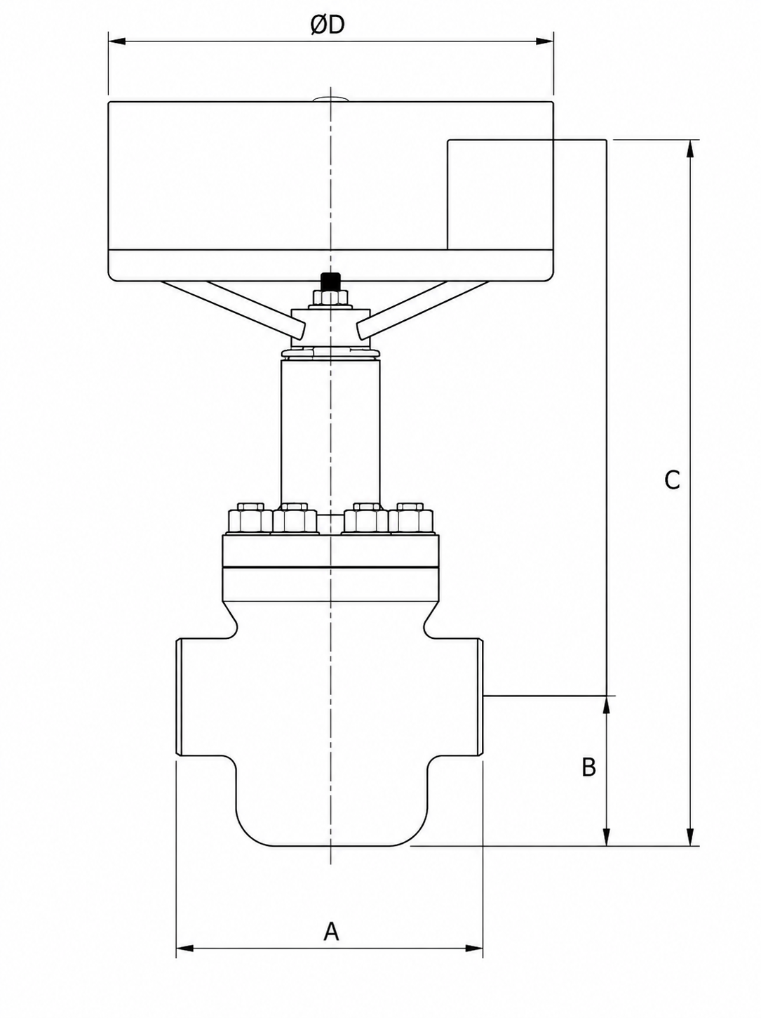
Figure 1 — CAMTOP Model M Gate Valve dimensional reference showing measurement points A, B, C, and D
2,000 PSI Working Pressure Rating
3,000 PSI Working Pressure Rating
5,000 PSI Working Pressure Rating
Dimension Reference Guide
AThread face-to-face dimension (end-to-end length of valve body)
BBore centerline to bottom of valve body
CBore centerline to top of hand wheel assembly
DHand wheel diameter for operation
Oilfield Applications
- Wellhead isolation and primary flow control systems
- Christmas tree (Xmas tree) installations and kill wing valves
- Manifold systems, choke manifolds, and flowline headers
- Production testing and high-pressure fluid handling
- Drilling rig floor equipment and workover operations
- Safety system integration and emergency shut-off circuits
Materials & Construction Standards
Body & Bonnet
Forged alloy steel (AISI 4130/4140), heat-treated for optimal strength and corrosion resistance.
Stem Assembly
High-strength alloy steel with hard chrome plating or Stellite coating for wear resistance.
Gate & Seat Set
Hardened alloy steel (HRC 48-55) or stainless steel 316, precision-lapped for bubble-tight sealing.
Stem Packing
High-temperature resistant graphite or PTFE V-ring set, operating range -29 to +121 deg C.
Handwheel
Ductile iron or steel construction with anti-slip grip pattern for field operation.
Bolting & Fasteners
ASTM A193 B7 stud bolts with A194 heavy hex nuts per ASME B31.3.
Operating Principle
The CAMTOP Model M operates as a wedge-type rising stem gate valve. The gate moves perpendicular to the flow path, seating against precision-ground seat faces to achieve a metal-to-metal seal.
Opening Procedure
Rotate the handwheel counterclockwise (CCW). The rising stem assembly translates rotary motion into linear travel, retracting the wedge gate from between the seats until fully retracted into the bonnet area. At this point, the full-bore opening provides unrestricted flow with minimal pressure drop.
Closing Procedure
Rotate the handwheel clockwise (CW). The stem descends, driving the wedge gate into the tapered seat cavity. Apply sufficient torque until firm resistance indicates a bubble-tight metal-to-metal seal. Avoid excessive over-torque.
Important Operating Note: Gate valves must be operated fully open or fully closed only. Partially open positioning causes accelerated erosion of gate and seat surfaces. For throttling or flow regulation, use dedicated CAMTOP needle valves or adjustable chokes.
Maintenance & Inspection Guidelines
- Packing Inspection: Check stem packing for leakage at every maintenance interval. Re-tighten gland nuts or replace packing set if needed.
- Handwheel Lubrication: Verify smooth rotation without binding. Apply anti-seize lubricant to threads and yoke bushings at scheduled intervals.
- Visual Inspection: Examine body flanges, bonnet connection, and end threads for corrosion, cracks, or damage before each installation.
- Pressure Testing: Conduct hydrostatic shell test at 1.5x working pressure and seat test per API 6A / API Spec 6FA annually.
- Seat Replacement: Replace worn gate and seat assemblies when leakage exceeds limits. Always replace matched sets together.
- Storage Protocol: Store in clean, dry environment with internal cavities coated rust-preventive compound and ends capped.
Quality Assurance & Compliance
All CAMTOP Model M Gate Valves are manufactured under ISO 9001:2015 and API Q1 certified quality management system. Each valve undergoes:
- Full hydrostatic shell and seat testing at factory-rated pressure
- Dimensional inspection per API 6A tolerance requirements
- Material traceability with certified mill test reports (MTR)
- NACE MR0175 compliance available for sour service environments
- Fire-safe design testing per API Spec 6FA where specified
Frequently Asked Questions
Contact CAMTOP for Quotation & Technical Support
- Phone / WhatsApp: +86-18621723891
- Email: SALES@CPOSL.COM
- Website: www.camtop-oilfieldtools.com
Reviews
There are no reviews yet.